
Add an HDMI input interface to your Raspberry Pi and record or stream high quality video from your HD camcorder with clean HDMI output
With the camera board, the Raspberry Pi supports video capture and processing applications. However, there is a limitation. Video can only be captured from the integrated camera. This HDMI In Video Capture Module expands on this idea, as it allows you to connect almost any HDMI video source to your favorite little Raspberry Pi computer. This opens up a new world of applications. Just use your imagination.
This project has been launched on March 12, 2014 on Kickstarter. Due to technical problems as outlined below it was stopped in late March. Since then his module has been rearchitected to support the Raspberry Pi, by integrating a hardware encoder. A new kickstarter project will be restarted soon. Please find all the details there:
https://www.kickstarter.com/projects/1419380698/connect-your-hd-camcorder-to-your-raspberry-pi
Why it is not possibly to feed uncompressed HDMI video into the Raspberry Pi?
After we have started this kickstarter project it was brought to our attention, that the Broadcom BCM2835 processor is only designed to take the video input from an image sensor as used on the camera board. The integrated video processor in the BCM2835 performs video processing functions specifically for these type of sensors, to create a clean video. The HDMI input chip already creates a clean video. As the video processing for the camera cannot be disabled at this time, a clean video cannot be interfaced to the serial camera interface (the MIPI/CSI connector). This is a show stopper. After further investigations we have concluded that this cannot be overcome. At this point of time it is not possible to get the video from an HDMI input via the CSI interface into the Raspberry Pi. Unfortunately the Raspberry Pi is not architected for such an application.
What is the new plan?
The HDMI video is compressed on this module and send as a compressed stream of data via USB to the Raspberry Pi. The H.264/AAC codec module (38079) is only 17.5 x 35 mm in size. It is plugged on top of the extended HDMI In module (38082). A short USB cable runs from the HDMI in module (micro USB) to the dual USB connector on the Raspberry Pi. The Raspberry Pi receives the compressed video via V4L2. In this manner the MIPI/CSI limitations of the Raspberry Pi are overcome.

Second generation HDMI in module with integrated H.642/AAC encoder (April 2014)
This module features 2 operating modes:
- it plugs on top of the Raspberry Pi and is operated in slave mode. The devices on the module (HDMI in and out) are configured by the Raspberry Pi. The encoder is controlled via USB.
- it is operated standalone in master mode. The onboard micro controller configures the devices. The encoder is controller via USB. The module is powered by USB.
In the standalone mode, this module my be used in conjunction with other computing platforms. At first x86 based Linux systems will be supported.
2nd generation HDMI in (36079 and 38082)
The following changes have been made to the first generation system. The 1st generation system (38068) has proven that the HDMI in and out section is working very well. Just the MIPI/CSI interface to the Raspberry Pi could be be brought up.
- MIPI/CSI interface was replaced by onboard H.264/AAC encoder
- compressed data is send to host system via USB
- slave mode or master mode (standalone mode USB powered)
- RS232 interface to Raspberry Pi or microcontroller (3.5mm jack)
Status
- design and layout completed in April 2014
- first prototypes (August 2014)
- production (early 2015)
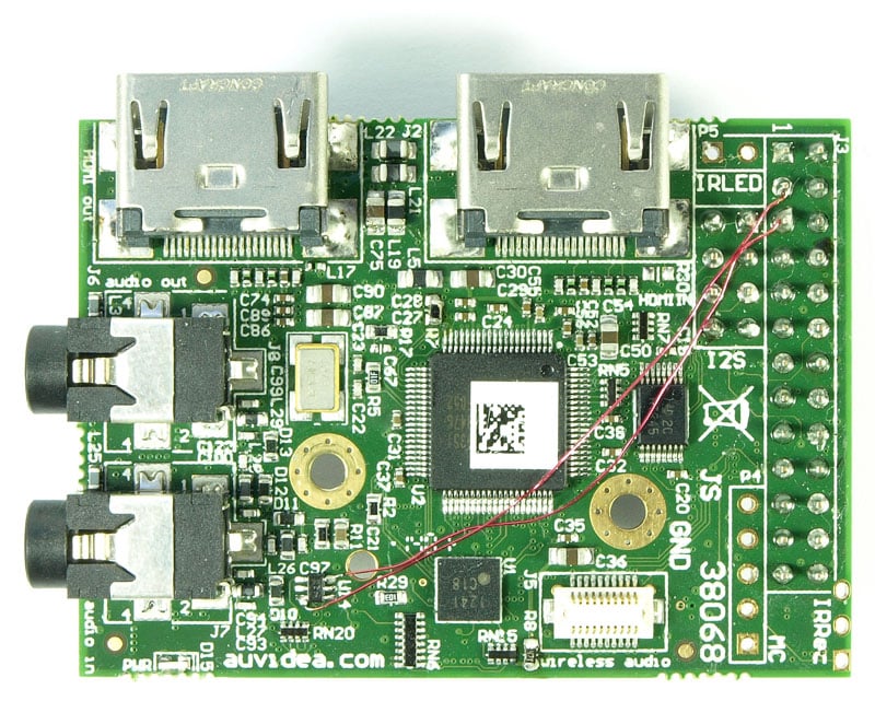
1st generation HDMI in (38068)
This system is outlined below and has been replaced by the 2nd generation system above.

Top view of the first prototype board (Feb 2014)
Bottom view of the first prototype board (Feb 2014)

Easily capture video from the following devices
- HD camcorders
- desktop or notebook PC
- game consoles such as Playstation 3 or XBOX 360
- many DVD players (with HDMI out)
- HDMI video input (converted to MIPI/CSI for the Raspberry Pi camera interface)
- resolution up to 1080p
- HDMI video output (splitter function: HDMI In forwarded to HDMI Out)
- HDMI embedded digital audio (stereo) to I2S bus of the Raspberry Pi
- optional analog audio in (line or mic with mix power for electret microphones): interfaced to I2S interface
- headphone audio out
- audio level meter with 8 LEDs (6 green, 1 yellow and 1 red)
- IR receiver (RC5) for infrared remote control
- IR transmitter (IR LED)
- socket for digital wireless 2.4GHz audio module (up to 4 channels: 2 transmit and 2 receive)
- compatible to pixel2media wireless audio body pack) and wireless audio headset with microphone
- connects to Raspberry Pi with 15 pin FPC cable (included)
Timing analyzer
The integrated timing analyzer allows to determine the timing parameters of the HDMI video input signal. This is very handy for the automatic configuration of the video processing software. For the printout below, an Apple iPad 4 was connected. It defaults to a video resolution of 720p60.

Micro controller
On board programable 32 bit micro controller (STM32F051 ARM Cortex M0 with up to 48 MHz – 32 bit RISC processor) for GPIOs (incl. LED level meter), IR receiver, IR transmitter, HDMI CEC, and HDMI I2C (DDC). ST provides a low cost discovery kit for STM32F051 line – with STM32F051R8 MCU (the STM32F0DISCOVERY). It connects to the module with a 5 pin ST-LINK cable. Atollic provides target-specific software development support (Eclipse based). We expect that the micro controller is fast enough to sense the I2C bus on the HDMI input (DDC) in software. So we plan to write a utility to scan and analyze the DDC bus.
Models
- HDMI in and embedded audio only (w/o micro controller)
- analog audio, IR receiver and transmitter, LED level meter and wireless digital audio socket (with micro controller)
- full version with all functions above
Important note
The HDMI input to this module must not be copy protected with HDCP. Some camcorder models and DVD players enable HDCP by default. This board will not be able to capture any video content, which is copy protected with HDCP. Sony camcorders are typically not supported as they output the HDMI video with HDCP protection. This is not really required but apparently it was Sony’s decision to do so. Panasonic camcorders are typically fully compatible, as their output is not protected with HDCP. We have tested multiple models such as the HC-V100, HC-V110, HC-V210, and HC-X929.
Software
The HDMI in and HDMI out chip are configured via the I2C bus. It turned out however, that the HDMI in chip requires a special I2C protocol which the I2C library of the Raspberry Pi can not support. The I2C command only allows to read and write up to 32 bytes from a single I2C address. The HDMI In chip however requires that 256 bytes are written, to initialize the 256 byte EDID memory, which is an integral part of the HDMI in chip. As a quick workaround the I2C bus was reconfigured as GPIOs and a bit banging scheme was used to write and read the 256 bytes. As a surprise it was really fast and it seems to work very well.
Last, the on chip registers of the HDMI out chips could not be read with the standard I2C read command. So a special I2C command was developed – again using bit banging. This is not performance critical, as registers mainly need to be read only in the debugging phase.
We invite programmers to enhance the I2C commands, so the specific demand of the HDMI in and out chips are directly supported.

View from the top


The side view shows the LED meter, which is located on the bottom side of the board. The 26 pin connector to the Raspberry Pi is not mounted in these images. The IR receiver and transmitter are not shown.